RISA
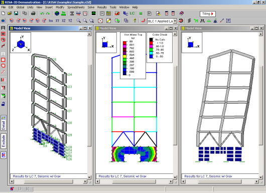
You may have multiple views of the model open at the same time, each with it’s own characteristics.
For example you can simultaneously view and work with
To Open a New View or Clone an Existing View
 button.
Alternately, you can open a new view that is an exact replica of the current
view by clicking the Clone View
button.
Alternately, you can open a new view that is an exact replica of the current
view by clicking the Clone View button.
Note
The two main tools to help you manipulate the views of the model are the Window Toolbar and the Model Display Options.


The Window Toolbar, discussed in this section, is the second
toolbar from the top when a model view is active. You may use these buttons to
rotate the model, zoom in and out, render the model, and display common
items such as
The Model Display Options Dialog (See Model Display Options for more information) is opened by
the first toolbar button  and provides various
options not otherwise available on the toolbar. It allows you to
specify how to plot
and provides various
options not otherwise available on the toolbar. It allows you to
specify how to plot
The Snapshot tool  is a great way to add images of model views and detail reports in your report printing. See Printing for more information.
The remaining buttons on the Window Toolbar help you change the viewpoint by rotating, snapping, and zooming the view. You may use the scroll bars and the mouse wheel (if you have one) to pan the view.
Note

 button or press the + key.
 button or press the - key.
 button
and then draw a box around the zoom area by clicking and dragging with
the left mouse button.
button
and then draw a box around the zoom area by clicking and dragging with
the left mouse button. button.
The Graphic Editing Toolbar or Drawing Toolbar may be turned on to graphically edit the model at any time and it may be turned off to provide a larger view. See Graphic Editing for more information.
To Toggle the Graphic Editing Toolbar
 button on
the Window Toolbar.
button on
the Window Toolbar.Click the  button to save and recall views.
If you have a view that you like to work with or have created a
view that took some time to set up, save it with this feature. All of the Model Display Options are saved
with the model for later recall. See Saving and Retrieving Model Views for more information.
button to save and recall views.
If you have a view that you like to work with or have created a
view that took some time to set up, save it with this feature. All of the Model Display Options are saved
with the model for later recall. See Saving and Retrieving Model Views for more information.
You can clone a view. This allows you to preserve the original view and modify the clone. This is useful in achieving two views that have similarities in some way.
To Clone the Model View
 button on the Window Toolbar.
Use these buttons  to control the display of loads. You
may display
to control the display of loads. You
may display
The last buttons on the Window Toolbar are toggles that plot information in the current view.
Click  to toggle model rendering.
See Model Display Options for more information on rendering.
to toggle model rendering.
See Model Display Options for more information on rendering.
Click  to toggle the
joint
labels.
to toggle the
joint
labels.
Click  to toggle the
member
labels on and off. If rendering is on, member labels will not be visible.
to toggle the
member
labels on and off. If rendering is on, member labels will not be visible.
Click  to toggle display of member color basis.
Click  to toggle display of deflected shape.
Click  to
toggle the I-J end flags.
to
toggle the I-J end flags.
Click  to toggle display of member results.
Click  to
toggle the boundaries.
to
toggle the boundaries.
Click  to toggle the global
axes orientation on and off in the view.
to toggle the global
axes orientation on and off in the view.
Click  to use the distance tool.
Click  to toggle display of reactions and moments.
Right click in the model view and click Depth
Effect on the Shortcut Menu to access the depth effect options.
Depth effect is used to increase or decrease the "depth" effect
of the plot. Increasing the depth effect causes points farther away
from the screen to converge towards a vanishing point, giving the image
a more realistic three-dimensional appearance. Removing the depth
effect causes the vanishing point to become infinity (no vanishing point).
The button resets the view to have no
depth effect.
You may want to view only part of your model, especially if it is a big one. You may use the selection tools to give you the view that you want. You can graphically unselect parts of the model that you don't wish to see, or you can use a range of coordinates or other criteria to specify what to view. See Graphic Selection for more information.
You can save and recall views for a model. Saved views are model dependent so any views you save will stay with the model. A saved view includes information such as the current view angle, zoom state, pan location, plot option settings, etc. Saved views do NOT include the selection state for the model. You can save selection states separately. See Saving Selections for more information.
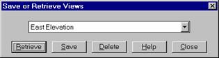
To Save the Model View
button on the Window Toolbar.To Retrieve a Saved Model View
button on the Window Toolbar.To Delete a Saved Model View
button on the Window Toolbar.